
Effective fireproofing of industrial buildings protects load-bearing steel and concrete long enough for safe evacuation, emergency shutdown, and firefighting. Understanding how fire ratings, hazard zones, and material selection work together is essential to preventing structural collapse during a fire.
Key takeaways
- Fireproofing is a method (insulating a structural element). A fire rating is a performance result (hours achieved in a standard test). Code gives you the rating; the material and thickness deliver it.
- Unprotected structural steel keeps only about 60% of its yield strength at 550 °C and about 47% at 600 °C. It does not burn, but it does not stay up either.
- In process plants you do not fireproof everything. You fireproof what lies inside a defined fire-scenario envelope, plus what the plant needs to shut down safely.
- Most site failures come from application, not product: wrong primer, low thickness, unsealed edges and open penetrations.
1. What Fireproofing Really Means
Fireproofing is the application of insulating materials to structural members, supports and critical equipment so they keep their load-bearing capacity for a defined time in a fire. It is one part of passive fire protection (PFP), which works without power, detection or human action.
Two terms are often mixed up:
| Term | What it is | Example |
| Fireproofing | A physical method or material | Epoxy intumescent on a pipe rack column |
| Fire rating | A tested performance, in minutes or hours | A column that survives 2 hours of standard fire exposure |
A rating can be met with no fireproofing at all. A thick RCC wall or a solid fire door achieves its rating through its own mass and design. For a structural steel column, the coating is what gets it to the required hours.
Fireproofing also does not mean ignition resistance. Stopping combustible materials from igniting is the job of fire-retardant treatment. Stopping fire and smoke spreading between rooms is the job of compartmentation and firestopping. Fireproofing protects structural stability.
2. Why Steel Needs Protection
Steel is non-combustible, but its strength falls quickly with temperature. Using the Eurocode 3 (EN 1993-1-2) reduction factors for yield strength:
| Steel temperature | Yield strength retained |
| 400 °C | about 100% |
| 500 °C | about 78% |
| 550 °C | about 63% |
| 600 °C | about 47% |
| 700 °C | about 23% |

The figure of 550 °C is often quoted as the “failure temperature” of steel. Treat it as a traditional limiting value, not a physical constant. The true critical temperature depends on the load the member carries and how the section is heated, and for lightly loaded members it can be much higher. That is why designers calculate it case by case, using the section factor (Hp/A): thin, slender sections with a large heated perimeter per unit of steel area heat up faster and need thicker protection than heavy sections.
3. Know Your Fire: Cellulosic, Pool and Jet
The protection you need depends on the fire you expect.
| Fire type | Typical setting | Test or curve | Behaviour |
| Cellulosic | Offices, warehouses, general factories | ASTM E119 / UL 263, ISO 834, IS 3809 | Gradual rise, about 1,000 °C at around 2 hours |
| Hydrocarbon pool fire | Process units, tank areas | UL 1709 | Rapid rise to about 1,100 °C within about 5 minutes |
| Jet fire | High-pressure releases | ISO 22899-1 | Very high heat flux and erosive impingement |

Two points worth remembering:
- API 2218 is a pool-fire standard. Its own scope is pool fires. Jet-fire scenarios are handled through the annex and a fire hazard analysis, which can justify larger protection radii and more reliance on isolation and depressurisation.
- A product tested to a cellulosic curve is not evidence of hydrocarbon performance. Always check which curve the certificate refers to.
4. Fire Ratings in Indian Building Codes
Fire and life safety in Indian buildings is covered by Part F of the National Building Construction Standards 2026 (NBCS 2026, SP 7:2026). It replaced the National Building Code of India 2016 in April 2026, and Part F takes the place of the old Part 4. Older drawings, specifications, and audit reports that cite “NBC 2016, Part 4” should now be read against Part F.
Part F describes itself as guidance. Fire services are a state subject, so its requirements become binding through state fire laws, building bye-laws, and the conditions of the fire authority’s NOC. Confirm which edition your state has adopted.
Ratings are set by construction type and element. Part F classifies construction into four types (Type 1 to Type 4) and gives minimum fire resistance ratings in minutes for each structural and non-structural element in its Table 1. A few examples for structure:
| Element | Type 1 | Type 2 | Type 3 | Type 4 |
|---|---|---|---|---|
| Columns, beams, girders, and framing supporting more than one floor | 240 min | 120 min | 120 min | 120 min |
| The same, supporting one floor only | 180 min | 90 min | 60 min | 60 min |
| The same, supporting a roof only | 180 min | 90 min | 60 min | 60 min |
| Floor construction | 120 min | 90 min | 60 min | 60 min |
| Bearing exterior walls | 240 min | 120 min | 120 min | 60 min |
Table 1 also covers non-bearing walls by fire separation distance, exit enclosures, service shafts, and roofs. The older shorthand of “4, 3, 2, and 1 hours” for Types 1 to 4 is a simplification and does not match these values.
Industrial occupancies. Industrial buildings fall under Group G: G-I (low hazard), G-II (moderate hazard), and G-III (high hazard), with Annex B giving a broad classification by fire hazard only. Hazardous and storage occupancies are separate groups (H and J in Part F; the two letters were the other way round in NBC 2016). Where different degrees of hazard exist in different parts of a building, the most hazardous governs, unless the hazardous areas are segregated or protected. Part F applies to industrial buildings above set thresholds: a total area over 2,000 m² for G-I and G-II, and 15 m height or 500 m² floor area for G-III. State and local authorities may modify these values.
Structural steel. Part F says load-bearing steel beams and columns in buildings with a total covered area of 500 m² or more need protection against failure and collapse in a fire, using suitable fire-resistance-rated materials together with a suppression system. Ratings must be validated and certified by test, and Annex C gives guidance where no certified rating exists.
Separation inside industrial buildings. Areas with storage, manufacturing, or hazardous activities, such as paint stores, oil storage, and spray booths, should be separated from non-hazardous areas such as offices and canteens by walls and doors rated 120 minutes. For high-hazard areas such as petrochemical and explosives, the rating is 240 minutes.
These ratings apply to buildings. Open process structures such as pipe racks follow the fire-scenario envelope approach in section 6.
The code sets the required minutes. Your design then decides how to achieve them: concrete cover, encasement, boards, sprays, or intumescent coatings. Confirm the exact clause in the edition your state has adopted and with the local fire authority.chieve them: concrete cover, encasement, boards, sprays or intumescent coatings.
5. RCC: Mostly Inherent, Sometimes Not Enough
Reinforced concrete is non-combustible and insulates its reinforcement, so RCC usually achieves its rating through member size and concrete cover rather than any applied coating.
- IS 456:2000, Table 16A gives nominal cover for fire resistance by member type and rating. For a simply supported beam, the tabulated cover rises from 20 mm at 1 hour to 40 mm at 2 hours. Columns are shown at 40 mm across the rating range. Continuous beams and slabs have lower values.
- Table 16A also carries minimum member dimensions. Cover alone is not enough.
- IS 456 requires the greatest of the durability cover (Table 16), the fire cover (Table 16A) and the bar diameter. In many Indian projects, durability cover governs.
- Added protection for RCC is justified when cover is deficient, when an older structure is being upgraded, or in tunnels and hydrocarbon environments where explosive spalling is a concern. Polypropylene micro-fibres (commonly around 1 to 2 kg per cubic metre) melt at roughly 160 °C and leave channels for steam to escape.
6. Where to Fireproof in a Process Plant
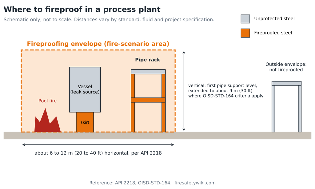
An industrial site is not fireproofed wall to wall. Standards such as API 2218 and OISD-STD-164 (Fire Proofing of Steel Supporting Structures in Oil & Gas Industry) use a fire-scenario envelope: the zone around equipment that can leak and sustain a fire.
Typical envelope practice
- API 2218 describes the envelope as roughly 6 to 12 m (20 to 40 ft) horizontally from fire-potential equipment.
- Insurer guidance (AXA XL) is similar in spirit: first-level pipe rack supports within about 7.6 m of heaters, pumps, towers and major flammable-liquid vessels are protected, with lighter protection out to about 15 m and generally none beyond.
Typical elements covered
| Element | Common practice |
| Pipe racks | Columns, girders and load-bearing bracing up to the first pipe support level; OISD-STD-164 extends this to the level nearest 9.1 m where lines larger than 6 inches are carried above, or where large hydrocarbon pumps sit beneath |
| Pipe racks carrying fin-fan coolers | Columns to the equipment support level, plus members carrying the equipment load |
| Vessel skirts, sphere legs, equipment supports | Full load-bearing height inside the envelope |
| ESD valves, actuators, critical cables | Protected for the time needed to isolate and depressurise, typically stated in the project specification |
| Pipe racks outside the hazardous area | Not fireproofed |
Insurer guidance often cites 3-hour protection for main structures and equipment supports and 1-hour for cable and piping supports. Treat these as benchmark values and follow the project specification.
What usually does not need it: maintenance walkways, ladders and handrails, and small utility line supports that carry no hazardous material and do not support main frames.
Risk-based reduction. Prescriptive distances are a starting point. A quantitative risk assessment with thermal radiation modelling, backed by emergency shutdown, blowdown and deluge, can justify a smaller scope. Any such deviation needs documented analysis and formal approval. Never assume that a deluge system replaces fireproofing; it is a supplement unless the engineering case says otherwise.
7. Choosing the Material
| System | Best suited to | Watch out for |
| Cementitious spray (SFRM) | Concealed indoor steel, cost-sensitive areas | Rough finish, moisture uptake and cracking in corrosive outdoor service |
| Water-based thin-film intumescent | Exposed indoor steel where appearance matters | Not suited to harsh chemical or weathered environments |
| Two-component epoxy intumescent | Outdoor process plant steel, hydrocarbon and jet-fire exposure | Needs mesh in many systems, careful application and compatible primer |
| Boards and casing | Cable trays, ducts, columns | Joint detailing and fixings |
How intumescents work. The coating combines an acid source (for example ammonium polyphosphate), a carbon source such as pentaerythritol and a blowing agent such as melamine. When heated to roughly 200 °C and above, it reacts and swells into an insulating char many times its original thickness.
Colour does not matter. Fire resistance comes from chemistry and dry film thickness, not pigment. Base coats are usually white or off-white. A coloured topcoat is acceptable only if the manufacturer approves it, because the wrong topcoat can restrict expansion.
Timber and wood are treated differently: pressure impregnation with fire-retardant salts such as phosphates, borates or boric acid, or surface fire-retardant coatings. This controls ignition and flame spread rather than giving structural fire resistance.
8. Corrosion Under Fireproofing (CUF)
Fireproofing that traps water destroys the steel it protects. To manage CUF:
- Use an approved anti-corrosive primer, commonly a zinc-rich epoxy, compatible with the fireproofing system.
- Seal tops and terminations with elastomeric sealant, detailed to shed water.
- Specify and inspect around bolted connections, penetrations and supports where water collects.
- Include fireproofed steel in the plant’s inspection programme. Repairs are easier before corrosion has progressed.
9. Field Inspection Checklist
Surface preparation
- Steel abrasive-blasted (commonly Sa 2.5 / SSPC-SP10) and free of oil, grease, mill scale and loose rust.
- Primer is listed on the fireproofing manufacturer’s compatibility chart, and its dry film thickness is within the vendor limit.
Conditions during application
- Steel temperature at least 3 °C above dew point.
- Ambient temperature and humidity within the product datasheet limits.
Reinforcement
- Where the system requires mesh, confirm it is embedded within the coating, not bare on the steel or showing at the surface, and that laps meet the installation manual.
Thickness
- Required thickness matches the member’s Hp/A and the required rating, taken from the vendor’s third-party test chart (UL, Warringtonfire/Certifire or equivalent).
- Measure with a calibrated DFT gauge for intumescents and a depth gauge for cementitious spray. Acceptance limits for individual and average readings are set by the project specification and vendor approval; do not assume a fixed percentage.
Finish and sealing
- Topcoat approved by the manufacturer.
- Edges and terminations sealed.
- Reject pinholes, mud-cracking, delamination, hollow-sounding areas and mechanical damage, including scaffold damage.
Firestopping
- Walk the site after trades finish. Every penetration through a fire-rated wall or floor should carry a tested firestop system. One unsealed cable gap can compromise the whole rated barrier.
10. A Practical Six-Step Workflow
- Define the fire scenario. Cellulosic, pool or jet?
- Define the protection zone. Code hours for buildings; a fire-scenario envelope for process areas.
- Match material to structure. RCC by cover, indoor steel by spray or thin-film, outdoor plant steel by epoxy.
- Verify thickness from third-party test data against section factor and rating.
- Control installation. Primer, DFT and edge sealing.
- Close the gaps. Firestop every penetration.
Rule of thumb: Design gives you the fire rating (hours). Material and thickness give you the fireproofing (millimetres). Edge sealing, firestopping and inspection keep it working for the life of the plant.
Frequently Asked Questions
Is fireproofing the same as fire rating? No. Fireproofing is the method; fire rating is the tested outcome in hours.
Does RCC need fireproofing? Usually not. It achieves its rating through size and cover. Extra protection is considered for deficient cover, upgrades or hydrocarbon fire exposure.
Does colour affect fire resistance? No. Thickness and chemistry do.
Can deluge replace fireproofing? Only where an engineering analysis and the governing standard allow it. It does not replace fireproofing by default.
Related Articles
- Passive Fire Protection (PFP) in High-Hazard Industrial Facilities: A Practical Engineering Guide
- Fire Water Demand in India: OISD vs IS 13039
- Water-Based Fire Protection Systems in Industrial Facilities.
- AZF Toulouse Explosion (2001): What Happened and the Lessons for Fertilizer Plants
- Hot Work Safety: Hidden Fire Hazards and Permit Controls
Further Reading
- National Building Construction Standards 2026 (SP 7:2026), Part F: Fire and Life Safety (replaced NBC 2016, Part 4)
- IS 456:2000 (Table 16A) and IS 3809
- API Publication 2218, Fireproofing Practices in Petroleum and Petrochemical Processing Plants
- OISD-STD-164, Fire Proofing of Steel Supporting Structures in Oil & Gas Industry
- UL 1709 and ISO 22899-1
- EN 1993-1-2 (Eurocode 3, fire design) and EN 1992-1-2 (Eurocode 2, fire design)
- SFPE Handbook of Fire Protection Engineering; ASFP “Yellow Book”
Pingback: Fire Water Demand in India: OISD vs IS 13039
Pingback: History of Fireproofing: From the Great Fire of London to Modern Fire Testing